
 首页
首页 登录
登录 注册
注册


HTML
-
High-entropy alloys (HEAs) consist of multiple elements in roughly equal atomic ratios or close to equal atomic ratios.[1] Through adjusting the types and amounts of elements, grain size, and preparation processes, HEAs can display outstanding properties including high strength, low density, corrosion resistance, wear resistance, superconductivity, and radiation resistance.[2–5] These attributes make them highly promising for applications in aerospace, military, and various other fields.
CoCrFeNiMn HEA is known as Cantor HEA, which is the earliest and most widely studied HEA.[1] By adjusting the ratio of Mn elements, CoCrFeNiMn HEA will exhibit different structures and mechanical properties.[6,7] Zhao et al.[8] found that CoCrFeNiMn HEAs exhibit lower hardness with increasing Mn content. Hashimoto et al.[9] revealed that the CoCrFeNiMn HEAs have higher stacking fault energy at higher Mn content. Furthermore, the formation of self-interstitial atom faulted loops in irradiated CoCrFeNiMn HEAs may depend on the Mn content. Chang et al.[10] used molecular dynamics (MD) simulations to research the effect of Mn on mechanical properties and deformation mechanism of polycrystalline CoCrFeNiMn HEA with a grain size of 6 nm. Compared with CoCrFeNiMn HEA, CoCrFeNi HEA showed the higher ultimate tensile strength, yield stress and Young’s modulus. In addition, atomistic modeling of CoCrFeNiMn HEAs indicates that the relationship between the melting temperature and Mn content does not conform to the behavior of a homogeneous solid solution, exhibiting a maximum value when the Mn content is 8.7 at.%.[11]
The shock compression response of HEA is of great concern to researchers because it involves applications under extreme conditions such as high pressure and high strain rate. Strain-rate effects and dynamic behavior of HEAs were reviewed by Huang et al.[12] Zhang et al.[13] conducted plate impact experiments on CrMnFeCoNi HEA with a heterogeneous structure to investigate its deformation and spall damage. They found that the heterogeneous structure does not lead to a significant increase in spall strength compared to the homogeneous structure. Qiao et al.[14] revealed the abnormal strength-plasticity enhancement and the suppression of high strain rate embrittlement of CrMnFeCoNi HEA during impact tensile process through split-Hopkinson tensile bar (SHTB). This was attributed to the key mechanism of cooperation of twins and dislocations. Zhao et al.[15] investigated the dislocation behavior in BCC HEAs under shock compression. An extended edge dislocation structure was observed in TiZrNb and NiCoFeTi HEAs which was different from BCC elemental materials Nb and Mo. Thürmer et al.[16] studied the impact fracture behavior of nanocrystalline HEA. Compared to single-crystal HEAs, the fracture strength of nanocrystalline HEAs is significantly reduced, with a large number of stacking faults, twins, and dislocations present during the shock compression and release processes. Li et al.[17] found that the grain boundaries serve as void nucleation sites and weaken the spall strength of nanocrystalline HEA. But the deformations in the grain interior are similar to those in the single-crystal HEA. Moreover, Li et al.[17] revealed that Mn seems to be the most influential element in the CoCrFeMnNi HEA, resulting in the most significant change in strength. Li et al.[18] studied the transition from Hall–Petch to inverse Hall–Petch behaviors in nanocrystalline HEA under shock loading. They found this transition is strongly dependent on the shock pressure as a result of the complex interplay among multiple competing hardening and softening deformation mechanisms. Liu et al.[19] researched the effect of crystal orientation on the impact plasticity of CoCrFeMnNi HEAs and found that Mn elements are relatively high in both BCC and disordered structures, playing an important role in the impact plasticity of CoCrFeMnNi HEAs. Wen et al.[20] showed that significant lattice distortion and local stress appear around the Mn element due to its relatively large atomic volume and potential energy, which makes a substantial contribution to the shock-induced plastic deformation.
Most studies of CoCrFeNiMn HEA focus on components in equal proportions. However, different elements contribute differently to plastic deformation. The relevant studies[17,19,20] found that the Mn element plays a dominant role in the shock response of CoCrFeNiMn HEA, but the quantitative effect of changes in its content on the mechanical properties is not clear.
Therefore, this study aims to quantitatively study the effect of Mn content on the shock-induced plastic deformation and spallation damage of CoCrFeNiMn HEA using MD simulations. This work is organized as follows: Section 2 provides the detailed description of simulation methods, Section 3 presents the simulation results and comprehensive discussion, and Section 4 summarizes the main conclusions.
-
The interaction between CoCrFeNiMn HEA atoms is described by the second nearest neighbor modified embedded-atom method (2 NN MEAM) potential function proposed by Choi et al.[21] This potential function has been successfully applied to the study of shock compression of HEA.[16,17,19,20,22] To evaluate the effect of Mn content on the shock response, CoCrFeNiMnx HEA with different compositions were built. For example, the CoCrFeNiMn20 represents 20-at.% Mn content. The contents of other elements (Co, Cr, Fe, and Ni) are the same. All the atoms are randomly arranged in the model. Firstly, a small FCC single crystal CoCrFeNiMnx HEA model with dimensions of 7.2 nm×7.2 nm×7.2 nm is established. This small model is used to study the structural characteristics and elastic properties of the CoCrFeNiMnx HEA. Figure 1 shows the effect of Mn content on the radial distribution function (RDF) and average atomic volume. RDF gives the probability to find atom in a shell of thickness dr at a distance r from a reference atom. It is defined as
where n is the number of atoms in the shell from r to (r+dr), and ρ is the mean atom density. Figure 1(a) shows that the peak value of RDFs decreases with the increase of Mn content. As the Mn content increases, the distance of the first peak becomes larger, indicating that the atoms are arranged more closely with a lower Mn content. The average atomic volume also quantitatively accounts for this phenomenon, as shown in Fig. 1(b). Moreover, Mn element has the largest atomic volume. When the Mn content is ≤ 20%, the atomic volume order of the remaining elements is Fe > Cr > Ni > Co. When the Mn content is 30%, the atomic volume of Cr is larger than that of Fe. The difference in average atomic volume will cause local lattice distortion in HEA, thereby affecting the mechanical properties. This is also the structural basis for the effect of Mn content on shock response, which will be discussed in detail in Section 3. A larger model with dimensions of 20 nm×20 nm×20 nm is also used to study the effect of sample size, which has almost no effect on the structural characteristics.
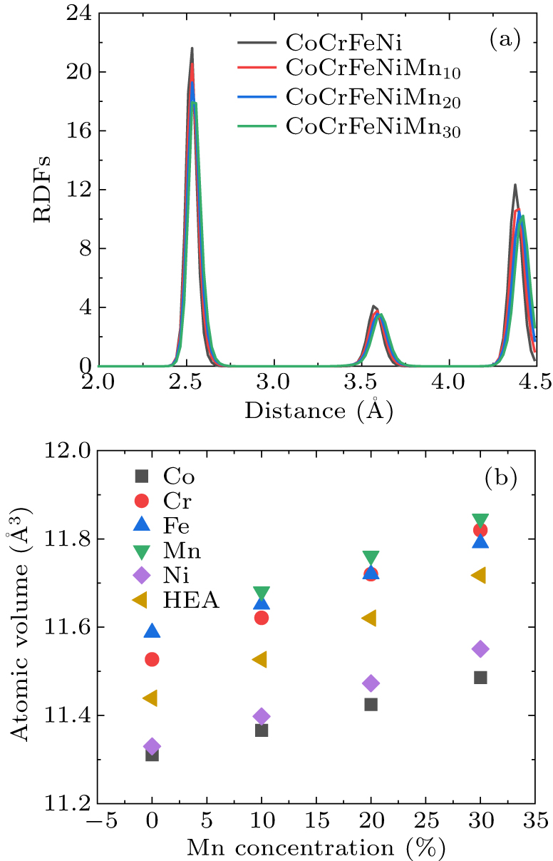
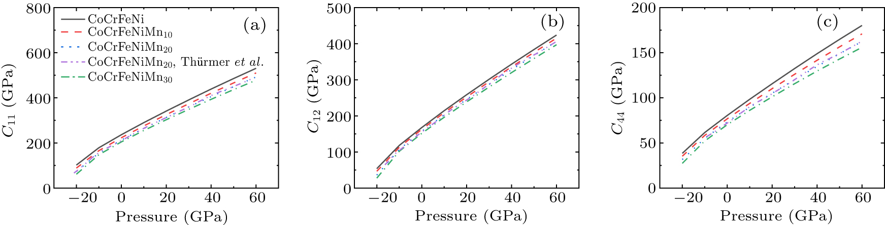
Figure 2 shows that the elastic constants behave consistently under deformation for different Mn contents. Using the Cauchy stability criteria,[22] the FCC solid is stable in the range from −20 GPa to 60 GPa of hydrostatic pressure. The results for the CoCrFeNiMn20 HEA are consistent with those in Ref. [22]. This study extends the conclusion to a broader range of Mn contents. Under the same pressure, C11, C12, and C44 decrease with increasing Mn content. This is because the larger atomic volume (Fig. 1) leads to a weakening of the interactions between atoms,[21] resulting in a decrease in the elastic modulus. Table 1 shows the density and other significant elastic constants at 0 GPa and 1 K.
The schematic diagram of the shock compression of the CoCrFeNiMnx HEA is shown in Fig. 3. The sample contains 1.92 × 10⁶ atoms. The crystal orientations in the x, y, and z directions are [100], [010], and [001], respectively. The length in the shock direction (x direction) is 108 nm. The length in the direction perpendicular to shock direction (y and z directions) is 14.4 nm. To ensure the uniform distribution of each element in the model, the model used for shocking contains 60 small models of 7.2 nm×7.2 nm×7.2 nm. Each small model uses different random numbers to randomly assign atoms of different elements. Energy minimization was first performed on the initial large-scale single crystal CoCrFeNiMnx HEA. Then the samples are equilibrated within the isothermal–isobaric ensemble (NPT) at 1 K and zero pressure for 30 ps. Li et al.[17] found that the HEA exhibited higher dislocation density at an initial temperature of 300 K compared to 1 K. Moreover, the shock pressure and shock wave velocity decreased with increasing initial temperature.[20] Here, a low initial temperature of 1 K is chosen to minimize thermal noise, thereby facilitating the analysis of defects.
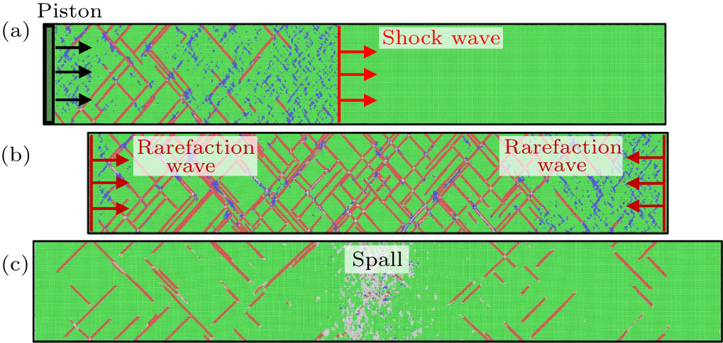
After equilibration, the shock wave propagation direction (x axis) is set as a free boundary, and periodic boundary conditions are imposed on the lateral surfaces (y–x and z–x). Shock waves are generated in the equilibrated HEA samples using the piston method,[23,24] as shown in Fig. 3(a). The 2-nm-thick slab located at the left edge (x axis) of the system is treated as the piston. Atoms inside the piston are assigned a uniform velocity along the x axis and zero velocity along the transverse axes. The piston velocity is ramped from 0 to Up within 2 ps to generate a compression wave within the sample. The final piston velocities Up are selected as 800 m⋅s−1, 1200 m⋅s−1, and 1600 m⋅s−1 to investigate the effect of different shock intensities. Atoms inside the piston are released when the shock wave reaches the opposite free surface. Rarefaction waves are generated from both free surfaces and move towards each other within the CoCrFeNiMnx HEA, as shown in Fig. 3(b). A tensile state is generated when they meet inside the sample. Subsequently, shock-induced spallation will occur within the sample, as shown in Fig. 3(c). Shock simulations are carried out in the microcanonical (NVE) ensemble with a time step of 1 fs.
To analyze the calculation results, the sample is divided into 0.5 nm thin layers along the shock wave propagation direction (x axis). Per-atom thermodynamic quantities are summed within each slab and over multiple time steps during the simulation. Then the sums are appropriately normalized to get one-dimensional profiles, which are outputted every 1 ps. The thermodynamic quantities used in the profiles include density ρ, temperature T, particle velocity up, and stress tensor Pij. The shock pressure is denoted as Pxx, and shear stress as Psh = 0.5[Pxx – 0.5 (Pyy + Pzz)]. The temperature T represents the kinetic temperature after subtracting out the center-of-mass velocity along the x axis.
Large-scale MD simulation code LAMMPS (large-scale atomic/molecular massively parallel simulator) is used in this study.[25] The dislocation extraction algorithm (DXA)[26] is used to analyze the dislocations. The polyhedral template matching (PTM) method[27] is used to identify the structures, with the root-mean-square deviation (RMSD) set to 0.1. All visualizations of atomic structures are performed using the software package OVITO.[28]
-
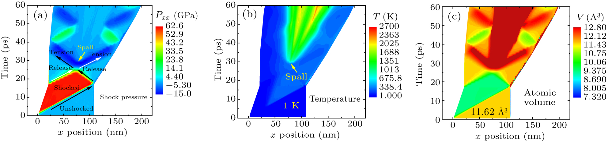
The spatial and temporal evolution of thermodynamic parameters are shown by position–time (x–t) diagrams in Fig. 4. The results for CoCrFeNiMn20 HEA at Up = 1200 m⋅s−1 are taken as a representative example. The arrows show the directions of shock wave propagation in Fig. 4(a). The pressure in the HEA rises sharply to 62.6 GPa due to shock compression. The shock wave reaches the right boundary at 17 ps and is subsequently reflected. At the same time, due to the release of the “piston”, a rarefaction wave is generated at the left boundary and propagates in the HEA. The pressure decreases in the region where the rarefaction wave passes. The two rarefaction waves meet in the middle of the HEA at about 25 ps. The tensile state causes the pressure to drop sharply until it reaches a negative value. Moreover, temperature and atomic volume rise sharply, as shown in Figs. 4(b) and 4(c). This indicates that spallation has occurred at about 28 ps within the HEA.
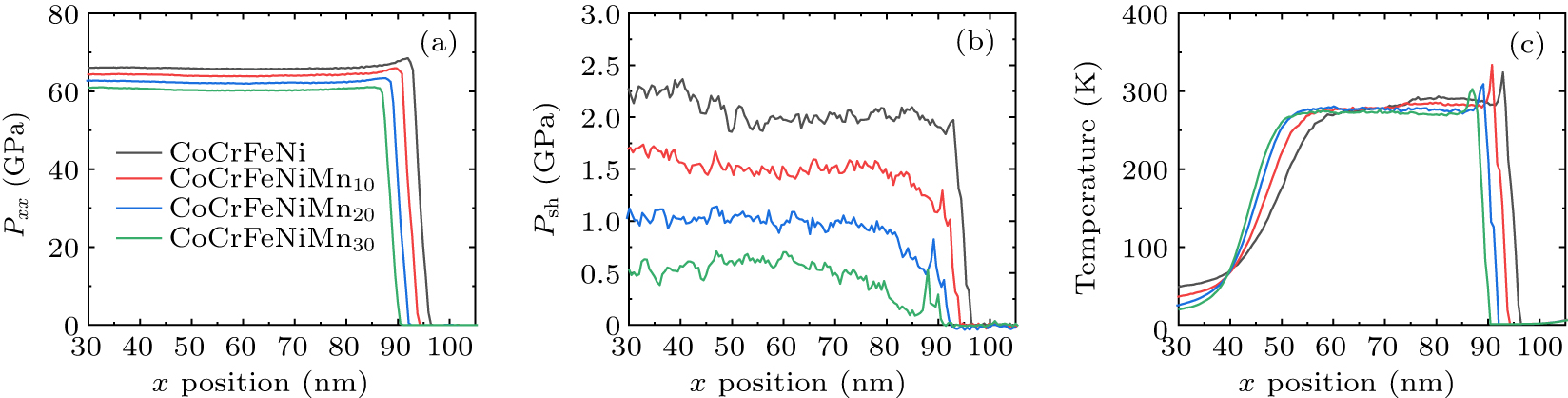
Shock wave profiles of the CoCrFeNiMnx HEA at Up = 1200 m⋅s−1 are shown in Fig. 5. The shock pressure decreases from 66.1 GPa to 60.5 GPa with increasing Mn content from 0 to 30%. This is consistent with the decrease in bulk modulus with increasing Mn content of the CoCrFeNiMnx HEA, as shown in Table 1. Figures 5(b) and 5(c) show that the shear stress and temperature also decrease with increasing Mn content. When the shock wave travels for the same time (15 ps), the x position of the shock wave front of the HEA with a lower Mn content is relatively larger, indicating that the increase of Mn content will lead to a decrease in the shock wave velocity Us. It is worth noting that the shock wave here is a plastic wave due to the large enough of Up (or shock pressure).
The shock Hugoniot curves represent the relationships between shock parameters in a material subjected to high-pressure and high-velocity shock. The Hugoniot Up–Us curves for different Mn contents are shown in Fig. 6(a). For each Mn content, the Up–Us curve exhibit approximately linear relationship of the form Us = c0 + sUp.
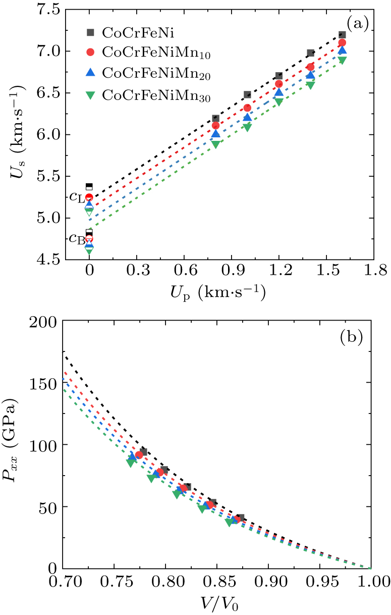
Table 2 shows the model parameters c0 and s for different Mn contents. Independent of Mn contents, s is approximately 1.25, indicating that the Up–Us curves has the same slope, as shown in Fig. 6(a). The value of c0 is located between the bulk sound velocity cB and longitudinal sound velocity cL. The value of c0 decreases with increasing Mn content. The Up–Us curves can be described as
where x is Mn content, which ranges from 0 to 30%. Based on the Up–Us curves, the dashed line in Fig. 6(b) shows the calculated Hugoniot curves P–V/V0, where the formula used is[29]
The MD simulation results (Fig. 6(b)) are consistent with the calculation Hugoniot curves P–V/V0 by Eq. (3).
-
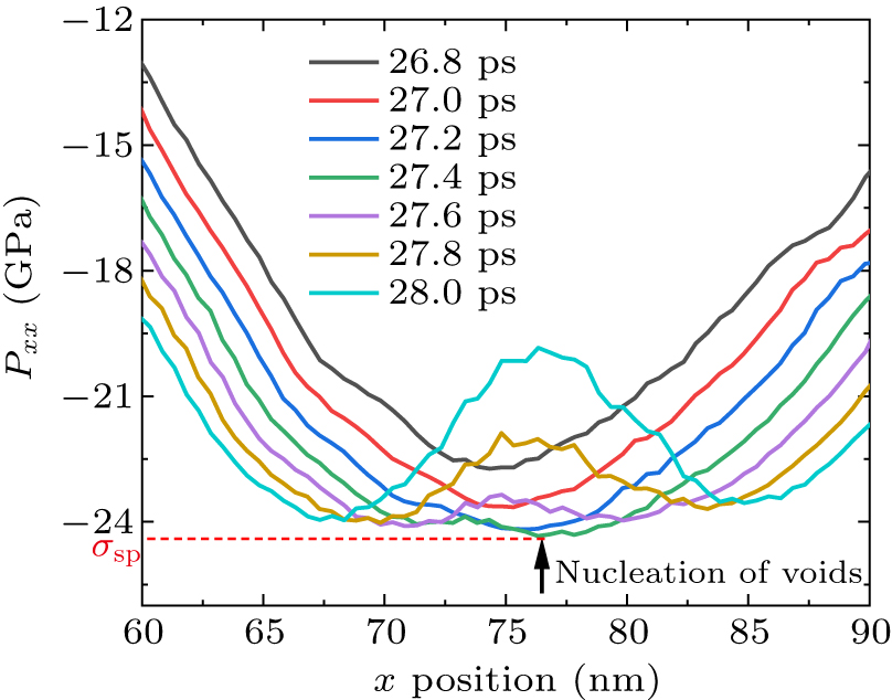
The Mn-dependent shock-induced spallation phenomenon of CoCrFeNiMnx HEA is studied in this section. Figure 7 shows the spatial distributions of Pxx for CoCrFeNi HEA sample at Up = 1200 m⋅s−1 during the spallation process. The tensile stress increases continuously until it reaches a maximum value at 27.4 ps. Then the tensile stress decreases significantly at x = 76 nm. This indicates the voids inside the HEA sample begin to nucleate and the spallation occurs. The maximum tensile stress is defined as the spall strength, σsp, as shown in Fig. 7.
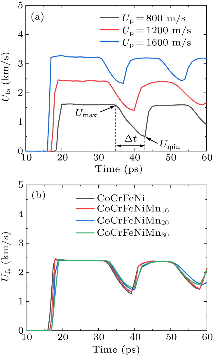
In experiments, the most common method to research the shock response is the analysis of the free surface velocity (FSV) as a function of time. Figure 8(a) shows the FSV histories of CoCrFeNiMn20 HEA at various Up. The spall strength can be deduced from ufs(t) as
where ρ0 is the initial density, umax and umin are the maximum and minimum velocities defined in Fig. 8(a).
The bulk sound velocity cB is chosen to be the sound velocity c here.[30] It is worth noting that this approach implies that the nonlinear contribution of the compressibility of the material is negligible, and there is only one constant sound speed in the material.[31] However, the nonlinearity has to be accounted for when the tensile stress is large. Thus, Kanel et al.[31] used extrapolation of Hugoniots in the pressure–particle velocity plane to the negative pressure region to obtain the spall strength:
where c0 and s are the model parameters in the relationship Us = c0 + sUp, which are shown in Table 2 for CoCrFeNiMnx HEA. Moreover, the corresponding strain rate is
where Δt is the time between umax and umin.
Figure 8(b) shows the FSV histories of CoCrFeNiMnx HEA at Up = 1200 m⋅s−1. Independent on the Mn contents, the maximum velocity umax are almost the same. However, the minimum velocity umin decreases with the increase of Mn content. Thus, Mn-rich CoCrFeNiMnx HEA should have a smaller spall strength based on Eq. (4).
Table 3 lists the strain rate (
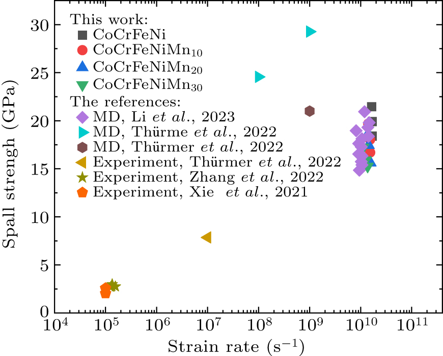
It is important to put the current results in context with other MD simulations and experimental data. Figure 9 shows the shock-induced spall strength as a function of strain rate ranging from 105 s−1 to 1010 s−1 for the CoCrFeNiMn HEA. Plate impact experiments[13,32] have the strain rate of approximately 105 s−1 with the spall strength of about 2.5 GPa. Laser-driven shock experiments[16] exhibit the strain rate of around 107 s−1 with the spall strength of about 8 GPa. For the MD simulations,[16,17,22] the strain rate ranges from 108 s−1 to 1010 s−1, corresponding to a spall strength ranging from 15 GPa to 30 GPa. Overall, the spall strength increases with increasing strain rate.
-
In this section, the effects of Mn content on shock-induced plasticity will be discussed in combination with analysis of microstructure evolution. Figure 10 shows the evolution of the fractions of different atomic structures over time. Shock compression stage is discussed first. When Up is 800 m⋅s−1, the structural transformation from FCC to HCP occurs due to the nucleation and development of dislocations. Meanwhile, a small amount of FCC to BCC transitions also occurs, as shown in Fig. 10(a).
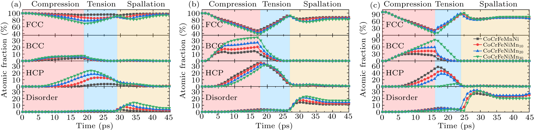
Figures 11(a)–11(c) show the structural changes at Up = 800 m⋅s−1. Some small BCC clusters appear under shock compression (15 ps), which can serve as nucleation sources for dislocations. The fraction of the HCP increases with the increasing Mn content. More shock-induced dislocations generate in the Mn-rich CoCrFeNiMnx HEA. When Up is 1200 m⋅s−1 (as shown in Figs. 10(b) and 11(d)–11(f)), approximately half part of the FCC transforms into the HCP and BCC at 17 ps. Moreover, the proportion of the BCC structure increases significantly, especially for Mn-rich CoCrFeNiMnx HEA. Figure 11(f) shows that some BCC structures gather together, which hinders the development of dislocations (HCP structures). When Up is 1600 m⋅s−1 (as shown in Figs. 10(c) and 11(g)–11(i)), the shock pressure is so high that almost all the FCC structures transform into the BCC structures for CoCrFeNiMn30 HEA under the shock compression. For CoCrFeNi and CoCrFeNiMn20 HEA, almost all the FCC structures transform to the HCP and BCC structures.
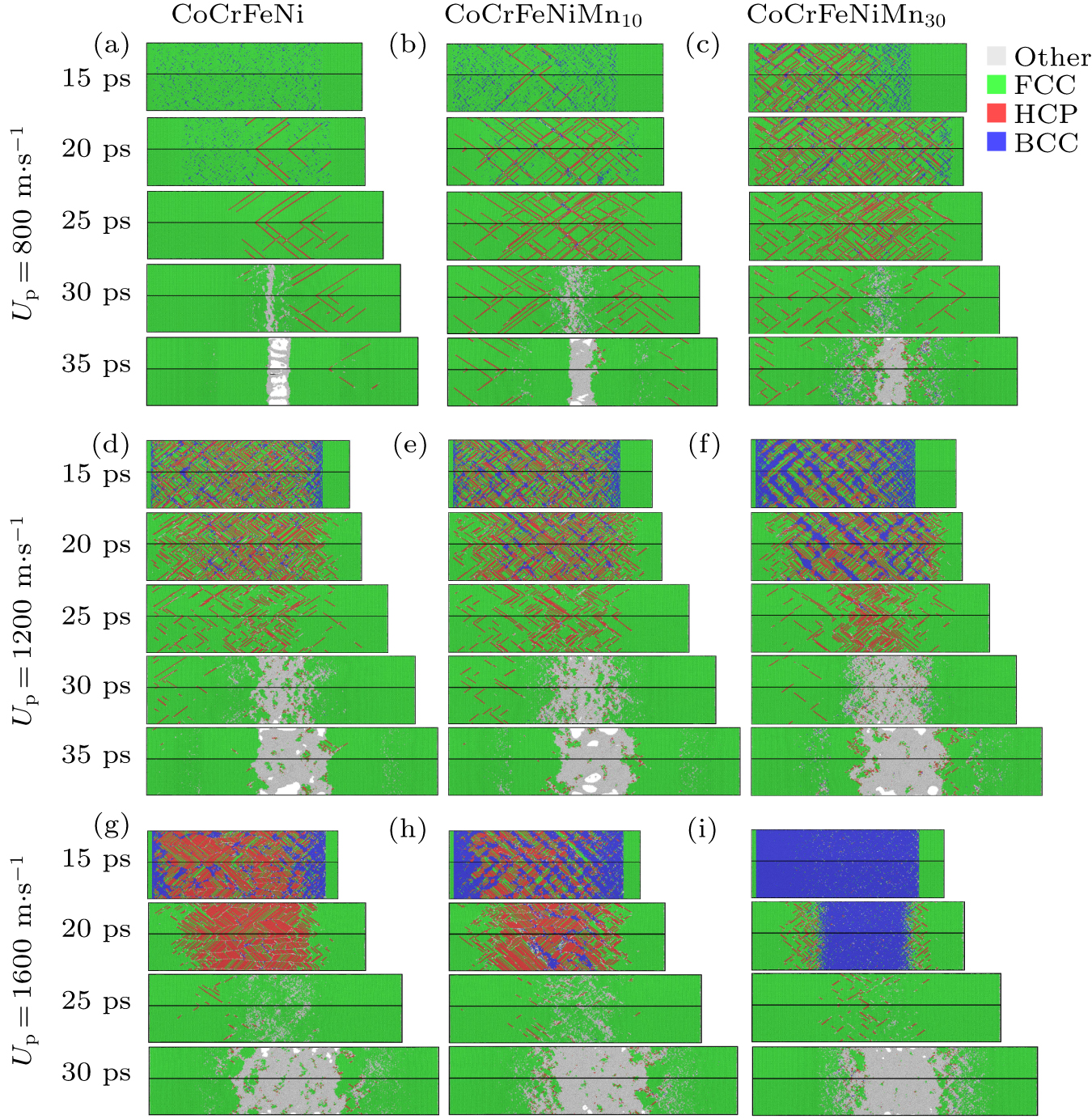
The structural transformation from FCC to BCC in CoCrFeNiMn HEA under shock loading has been reported in both MD simulations[17,19] and experiments.[33] The BCC atom comes from the body-centered-tetragon (BCT) structure formed between two FCC lattices.[17,19] In our work, due to the relatively high Mn content and the effect of high shock pressure, significant lattice distortions occur, resulting in the appearance of a large amount of BCC structures.
Under the tension (shock release) stage, HCP and BCC structures gradually return to the FCC structure, as shown in Fig. 10. Before spallation occurs, the fraction of BCC and HCP structures is almost zero. During the spallation process, FCC structures rapidly transform into disordered structures. The fraction of disordered structures reaches a maximum of 30% at Up = 1600 m⋅s−1. Figure 11 shows that a large number of disordered atoms appear around the spallation region in the middle of the sample. When Up is 800 m⋅s−1 and 1200 m⋅s−1, the increase in Mn content promotes the transformation of more FCC structures into disordered structures, making spallation more likely to occur. However, when Up = 1600 m⋅s−1, the higher shock pressure reduces this effect of Mn element. This is consistent with the characteristics of the changes in spall strength, as shown in Table 3. When Up is 800 m⋅s−1 and 1200 m⋅s−1, the spall strength σsp decreases from 26.2 GPa and 24.1 GPa to 19.3 GPa and 19.1 GPa with the increase of Mn content, respectively. The differences in σsp due to varying Mn content are 7 GPa and 6 GPa, respectively. However, when Up = 1600 m⋅s−1, σsp drops from 22.3 GPa to 18.9 GPa, with a difference of only 3.4 GPa.
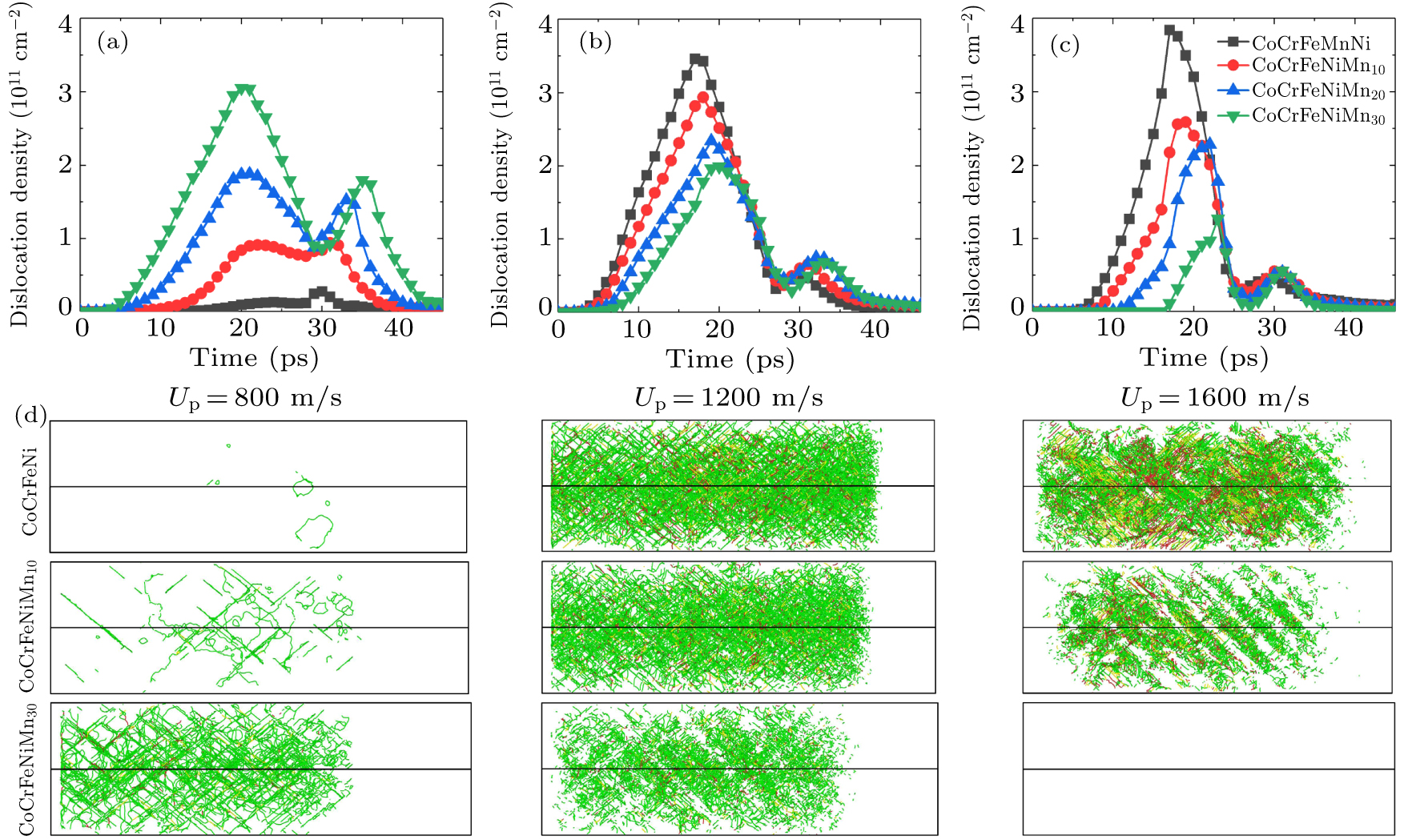
Understanding the evolution of dislocations is crucial for gaining deeper insights into the differences in plastic deformation behavior of CoCrFeNiMnx HEA. Figures 12(a)–12(c) illustrate the change in dislocation density over time. When Up is 800 m⋅s−1, the Mn-rich CoCrFeNiMnx HEA shows a relatively high dislocation density under shock compression, indicating that Mn promotes the nucleation and growth of dislocations. However, when Up is 1200 m⋅s−1 and 1600 m⋅s−1, the dislocation density decreases with increasing Mn content under shock compression. This phenomenon can be attributed to the structural analysis mentioned above (Figs. 10 and 11), which shows that the BCC structures inside the sample increases obviously with increasing Mn content. More importantly, these BCC structures tend to gather together. According to Figs. 11 and 12(d), the clustered BCC structures obviously hinder the development of dislocations, resulting in a decrease in dislocation density.
3.1. Thermodynamic quantities
3.2. Shock-induced spallation
3.3. Shock-induced plasticity and microstructure evolution
-
The effects of Mn content on elastic properties, shock profiles, shock Hugoniot relationship, shock-induced plasticity, and spall behavior of CoCrFeNiMnx HEA are investigated using MD simulations. The main research results and conclusions are as follows.
(i) The values of C11, C12, and C44 gradually decrease as the Mn content increases. This is due to the increase in average atomic volume caused by higher Mn content, weakening the interactions between atoms and thus reducing the elastic modulus.
(ii) The shock Hugoniot Up–Us curve of CoCrFeNiMnx HEA can be represented as Us = c0 + sUp, where s is approximately 1.25 and independent of Mn content. The parameter c0 is given by c0 = 5.21–0.011x, indicating that Us decreases with increasing Mn content at the same Up.
(iii) The Mn-rich CoCrFeNiMnx HEA exhibits lower spall strength. The increase in Mn content promotes the transformation of more FCC structures into disordered structures, resulting in spallation more likely to occur. However, the relatively high shock pressure reduces this effect of Mn element.
(iv) When Up is 800 m⋅s−1, the Mn-rich CoCrFeNiMnx HEA shows a relatively high dislocation density under shock compression. However, when Up is 1200 m⋅s−1 and 1600 m⋅s−1, the Mn-rich CoCrFeNiMnx HEA has more clustered BCC structures, which obviously hinder the development of dislocations, resulting in a decrease in dislocation density.
The Mn-dependent shock Hugoniot relationships can be used to design and optimize CoCrFeNiMn HEA materials for specific applications that involve high-velocity impacts, such as in aerospace, defense, and automotive industries. Additionally, the Mn-dependent shock-induced plastic deformations and spallation help in selecting CoCrFeNiMn HEA materials that can withstand specific shock conditions without failure.
 DownLoad: